|
|
|
|
Strategic Software Organization
Silicon Graphics, Inc.
655F Lone Oak Drive
Eagan, Minnesota 55121
ABSTRACT:
This paper describes the performance of GigaRing IO on CRAY T3E(TM), CRAY T90(TM), CRAY J90se(TM), and CRAY SV1(TM) systems, with recommendations on how to configure the IO for high performance.
GigaRing is a ring-based I/O system that connects Cray hosts (CRAY T3E, CRAY T90, CRAY J90se, and CRAY SV1) with I/O nodes for disks, tapes, and networks. It can also be used as a fast "System Area Network" (SAN). This paper presents examples of bandwidths measured on these hosts using IPI and Fibre Channel(TM) disks. It also presents CRAY SSD-T90(TM) and host-to-host TCP/IP bandwidths.
Software techniques listed in this paper for fast IO:
In this paper "JBOD" refers to "just a bunch of disks" individual disks. "RAID" refers to RAID-3 configurations with 4 data and one parity disks. These RAID provide parallel bandwidth and higher resiliency.
In general, RAID configurations provide a higher aggregate bandwidth than JBOD configurations, mainly do to a reduced interrupt load on the IPN or FCN processor. Choosing between JBOD and RAID is one of the more important configuration decisions that will affect performance.
GigaRing supports three classes of disks: IPI, Fibre Channel, and SCSI. IPN-1(TM) nodes are typically employed with reusing Model-E disks (DA-60, DA-62, and DA-302). FCN-1(TM) (Fibre Channel) nodes provide the highest bandwidth for the lowest cost. SCSI disks (DD-318) can be connected to GigaRing with MPN-1(TM) nodes. DD-318s were used before FCNs were available and are now used for small disks configurations.
CRAY T90 systems use SSD-T90 devices to buffer disk data in large DRAM memories.
RAID IPN disk provide better aggregate bandwidth than JBOD IPN disks. The RAID disks run at near peak speed while the JBOD disks may deliver only 50% of peak speed. RAID reduces the IPN interrupt rate, allowing the IPN node to deliver near the full bandwidth.
Each DA-60 RAID delivers about 80 MB/s. Each DA-302 RAID delivers about 35 MB/s.
For high bandwidth, one should limit the daisy-chaining of IPN disks to a depth of two. Deeper chaining will reduce the bandwidth delivered per disk. Combining striping and chaining will also reduce performance.
We recommend striping file systems with RAIDs, within an FCN node. The aggregate speed of RAID disks is faster than that of JBOD disks. As with IPNs, RAID reduces the interrupt load on the FCN.
One FCN node will connect 25 disks at full speed, arranged as 5 RAIDs of 5 disks (4 data + 1 parity) each. This configuration delivers 240 MB/s for reads and 160 MB/s for writes by striping the RAIDs with a width of 5.
Unstriped RAIDs deliver 1/5 of this speed: 48 MB/s for reads and 32 MB/s for writes.
If one connects multiple DA-308s to one Fibre Channel loop, the bandwidth increase is fairly flat. Reads increase from 48 MB/s to 62 MB/s per loop. Writes remain constant at 34 MB/s.
CRAY T3E systems support many GigaRing channels--a maximum of 8 or 16 PEs per channel. High-bandwidth file systems on CRAY T3E systems are striped five wide within a single FCN. This will group the RAIDs on a single GigaRing channel so they do not span packet and disk servers in UNICOS/mk(TM). Most CRAY T3E file systems should be buffered with pcache. Users should consider using FFIO and parallel IO techniques for maximum IO performance.
Each CRAY T3E-GigaRing interface will support 250 MB/s in and 250 MB/s out simultaneously. Typically they sustain over 200 MB/s in each direction, with a maximum of 320 MB/s in one direction at a time. Given these maximums, we recommend spreading FCNs across GigaRing channels, with one FCN per channel. This matches the near 250 MB/s bandwidth of an FCN.
The bandwidth for FCNs (with 5 DA-308s per FCN) distributed across multiple GigaRing channels scales well. For example ten FCNs (each driven from a separate PE) delivered an aggregate bandwidth of 2,300 MB/s for reads and 1,400 MB/s for writes. This is near ten times the 240 MB/s and 160 MB/s individual FCN bandwidth speeds.
Each processing-element (PE) in a CRAY T3E system will drive about 250 MB/s of bandwidth. This matches the bandwidth of 5-wide striped RAIDs on an FCN. For this reason, we do not recommend using a strip-width greater than 5 on RAIDs on CRAY T3E systems. For larger file systems one can band multiple 5-wide stripes.
Pcache is the main method used to buffer disk IO on CRAY T3E systems. It is similar to ldcache on UNICOS systems. Each operating system PE with a disk server can have a pcache.
One pcache delivers 239 MB/s for reads and 154 MB/s for writes. Additional pcaches on additional OS PEs increase the aggregate pcache bandwidth but the aggregate bandwidth is less than the bandwidth of one pache times the number of pcaches. For example, ten pcaches deliver 1,300 MB/s of bandwidth for reads (as apposed to 10 ~240 = 2,400 MB/s).
Note: all OS PEs (and therefore all pcaches) reside in a partial plane, not in main CRAY T3E torus.
CRAY T3E Operating System I/O
Data flows with minimum interruptions if related disk and packet servers reside on the same OS PE. This minimizes the interprocessor communications (IPCs), which have longer latency than intra-PE communication. Pcaches reside in the disk servers. This forms a relationship between the FCNs, GigaRing channels, packet servers, disk servers, and pcache servers. Placing the file server on the same PE as the disk server can also sometimes improve performance (depending on how many disk servers interact with that file server.)
One should therefore stripe 5 DA-308s on a single FCN. The path for this striped group would then be one packet, disk, and pcache server on a single PE.
File System Assistants (FSAs) typically improve reads but not writes. FSAs copy the file system information to the local PE to avoid IPCs for the individual file-system references. This works well for reads (when the file size and location remains constant) but can introduce a write penalty, if each write changes the size of the file. Most users do not preallocate writes so FSAs tend to have a write penalty. This is probably a reason that FSAs generally not in use in the field.
Performance is highest if disk and packet servers share an OS PE. If the disk and packet servers are on different PEs, they must use interprocessor communications (IPCs). If they are on the same PE, they can use intra-PE memory for communication. The latter has significantly less latency and overhead.
Pcaches (disk DRAM buffers) reside in the disk servers. One can therefore configure one pcache for every disk server in the system. The pcaches typically use the memory available on the OS PE (~100 MB in an 128 MB OS PE and ~500 MB in a 512 MB OS PE). Some sites purchase large memories (512 MB) for their OS PEs to maximize the pcache size. The maximum PE memory size is 2,048 MB, which limits the maximum theoretical individual pcache size to just under 2 GB.
The following is an example of a streamlined data path, with maximum file system bandwidth, minimum IPC overhead, and large pcache buffering:
UNICOS/mk allows one to configure multiple file servers (for multiple file systems). With 10 file servers and 25 PEs driving IO to 25 disks in each file server, a CRAY T3E systems delivered:
This data shows both the scalability of the file severs and the importance of preallocating files to minimize the write overhead.
File System Assistants (FSAs) can be used to distribute the file-system overhead to the user PEs. This tends to reduce the file-system overhead for well-formed reads and well-formed-preallocated writes. Unfortunately, not all users use well-formed reads or preallocated writes. For non-preallocated writes, FSAs add overhead, compared with not using FSAs. Therefore, FSAs are typically not used on most systems.
Each GigaRing channel will drive 200 MB/s in and 200 MB/s out simultaneously to a J90se interface. A CRAY J90se system has one GigaRing interface for each 4 CPUs, or a total of 8 interfaces on a 32 processor system. This is a theoretical maximum bandwidth of (200+200) 8 = 3.2 GB/s. With 200 MB/s of bandwidth per channel, we recommend distributing FCNs across the channels, if possible.
CRAY J90se systems use ldcache in central memory to buffer the disks. Ldcache is multithreaded for multiple IOs, but not for individual IOs. Individual ldcache IO streams run at 350 to 700 MB/s, depending on system load.
CRAY SV1 GigaRing channels have the same performance as CRAY J90se channels. A performance boost for these channels is planned for a second generation of CRAY SV1 systems.
Each CRAY T90-GigaRing interface will drive 425 MB/s in and 425 MB/s out simultaneously. CRAY T90 systems may have 8, 16, 24, or 32 channels, depending on the size of the frame and the number of CPUs. This is a theoretical bandwidth of (425 + 425) 32 = 27 GB/s. Again, one should distribute FCNs across channels, if possible, but with CRAY T90 systems this is less critical since a CRAY T90-GigaRing interface can drive multiple FCNs.
CRAY T90 GigaRing systems use CRAY SSD-T90 devices to buffer the disk data.
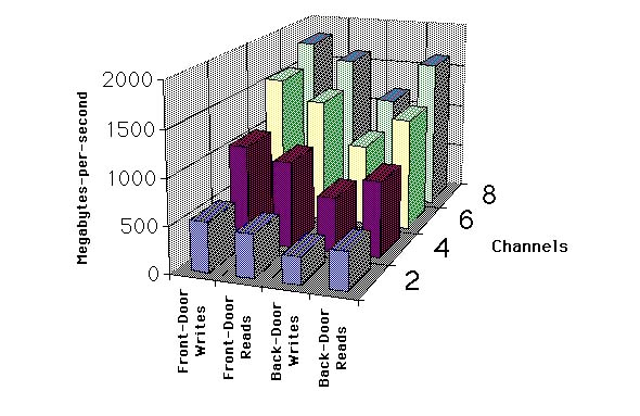
CRAY SSD-T90 devices are large DRAM buffers that reside on the GigaRing channels. The mainframe and the disks can pass their data through these buffers. CRAY SSD-T90 devices come with 2, 4, or 8 channels. Each channel typically delivers over 200 MB/s in and 200 MB/s out simultaneously. We tested an 8 channel system and demonstrated this bandwidth scaling across all 8 channels, for a total bandwidth in excess of 3 GB/s ((200 + 200) 8). The hardware and software overhead yields a latency of 70 microseconds per IO.
CRAY SSD-T90 devices are used as disk buffers (ldcache), secondary data segments (SDS for FFIO), SSD resident file systems, and swap.
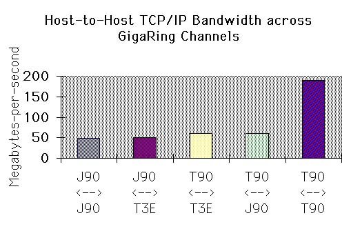
Recent releases of UNICOS(TM) and UNICOS/mk support TCP/IP protocols among GigaRing hosts over the GigaRing channels, without an intermediary network device, such as HIPPI. The bandwidth for these transfers it typically limited by the TCP/IP stack executing on the various speed processors. The following combinations yielded the following bandwidths:
The GigaRing technology is a high-end IO solution for CRAY T3E, CRAY J90se, CRAY T90, and CRAY SV1 systems. Most systems are configured with striped DA-308 (FCN) file systems for maximum performance. RAID disks tend to deliver better aggregate bandwidth than JBOD disks, because of the differing interrupt loads on the IO-Node processors.
One usually spreads the FCNs across multiple channels to avoid overloading any individual channel. For CRAY T3E systems, the maximum recommended stripe with is 5 DA-308s, to avoid overloading any individual PEs IO bandwidth. For CRAY J90se, CRAY SV1, and CRAY T90 systems, this restriction does not apply.
The following people produced most of the performance data in this paper:
![]()