Jan Julian
julian@arsc.edu

			http://www.arsc.edu/~julian/cug2004
Liam Forbeslforbes@arsc.edu
1 Introduction
In order to support the Department of Defense (DOD) High Performance Computer Program (HPCMP)
[1,1] Comprehensive Security Assessment (CSA)[1,2]
requirements, locally developed good security procedures and Arctic Region Supercomputing Center (ARSC) tools
that support monitoring of system changes, ARSC has found it necessary to modify the software
set initially installed on the machines that comprise the Cray X1 Complex.  In order to maintain the changes
that have been introduced, a backup and recovery system that will allow rapid recovery from failing
components of the X1 Complex or from changes introduced by human error is required.
This paper will briefly discuss the roles of the machines that comprise the X1 complex and the changes that ARSC
applied to these machines.  The backup and recovery method implemented on each of the platforms will be
described, as well as additional recovery requirements still in development.  Finally, we
will summarize problems that have not yet been resolved in relation to X1 Complex backup and recovery.
Portions of this paper discuss techniques and procedures that are in a state of development.  Some procedures
have been tested, others have not.  Some are in the planning stage awaiting further information.  Each procedure
will be identified as to its state of development.
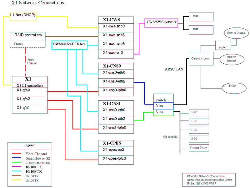
2 ARSC X1 Configuration
The X1 Complex for the purposes of this paper is considered to be the X1 Mainframe, Cray Programming Environment
Server (CPES), the Cray Network Subsystem (CNS), and the Cray Workstation (CWS).  At ARSC,
the X1 Complex consists of the X1, a CWS, a CPES, and two CNS machines, CNS0 and CNS1.  Figure (2-1)
offers a block diagram of the Complex and basic connectivity information.
Fig. 2-1 ARSC X1 Complex Connectivity (click on the image to enlarge)
In this configuration, the CWS is designed to operate and perform maintenance activities on a Cray X1 system,
that can run various levels of software [2,1].
In addition, it maintains centralized machine logging in the X1 Complex.
The primary purpose of the CPES is to provide good I/O bandwidth for compiling on the Cray X1 system through
trigger commands and native compiling [2,2].
The primary purpose of the CNS is to improve the network performance of Cray X1 computer systems.
[2,3]
It also provides, through IPtables, isolation of the X1 Complex from the public network.  Basically, the CNS operates as
a router, passing all packet traffic between site networks and the Cray Mainframe. The CNS OS is Redhat Linux,
in our case, at 2.4.18.  In addition, it installs with many features enabled beyond those that would be
required for router operation.
3 ARSC Modifications
ARSC has maintained a strong security posture in regard to its installed systems.  The earlier
"classic" Cray computers, the SV1EX and the T3E, installed at ARSC have undergone security
hardening procedures developed by ARSC and as such have had numerous changes made to the
file permissions, file ownership, and script content. Tools have been developed that monitor and
provide notification of changes in the status of the selected programs, scripts, and files.
In addition, a dump and restore capability has been developed to allow recovery should the systems
suffer catastrophic disk failure.  It was desirable to move these tools wherever possible to the
X1 Complex.
In addition to local requirements, the X1 at ARSC is affiliated with the DOD HPCMP and as such,
must comply with annual Comprehensive Security Assessment findings.  It is the case that the CSA has
treated each machine comprising the X1 Complex as being vulnerable to defined threat vectors as if each
was a standalone machine.  In addition, the Department of Defense occasionally announces Information
Assurance Vulnerability (IAV) Alerts, Bulletins, and Technical Advisories. [3,2]
ARSC is required to assess these for applicability to the ARSC systems and environment.  If either the
CSA findings or the IAVAs are deemed a vulnerability, action must be taken to mediate the threat.  These alerts
can result in the need to apply changes to the operating systems or cease operations.
For the most part, changes are addressed in a timely manner by Cray with the application of new release updates;
however, the nature of the CSA findings and IAVA assessments are such that applying patches, and in some cases removing
products from the OS and program set, produces substantial differences between the last current Cray release and the active
version installed at ARSC.  In some cases, running the systems without the applied patches, as in the case of a standard
reinstall, would not be allowed and would require the reapplication of all previous patches and modifications,
potentially a time consuming process.
In order to accommodate the traditional ARSC programming environment using /usr/local as the resident
directory for non Operating System libraries and programs, the CPES automount directory structure was changed.
The CPES had mounted the /usr  directory internally to allow the use of local libraries for compilation.
Doing so prevented the mount of /usr/local from the X1 in the /SV2 compile automount structure.  ARSC
modified the internal automount structure so that /usr/bin, /usr/css, /usr/lib, and /usr/local were mounted
individually.
On the CNS machines, the initial HPCMP CSA for these systems resulted in upgrades that
included the removal of ucd-snmp, sendmail, and bind.  Openssl,  glibc, and nscd were updated.  Additional
"hardening" steps included the modification to ownership and permissions of files that are typically modified by
ARSC system hardening.
In order to comply with HPCMP requirements, the release of openssh being installed on the X1 is the
current HPCMP openssh with patches that support the X1, SV1, and T3E.  It is different from the current COS
version.   ARSC has worked closely with Cray to incorporate changes introduced by the HPCMP into the
Cray Open Source openssh and will use, whenever possible the COS software. Occasionally, as  with this
release, the HPCMP version was installed quickly to mediate recognized threats.  Changes made at ARSC to the
HPCMP versions to support the X1, SV1, and T3E will be transmitted to Cray for their evaluation and
possible integration into future COS releases as well as to the HPCMP for inclusion in future HPCMP releases.
In the meantime,ARSC needs to be able to restore the modified version.
As the volume of modifications has grown, it has become necessary to provide a means to recover
the system environment on any of the X1 Complex machines in the event of failure.  Being unable to do so
means a prolonged period of recovery during which the X1 would not be available for work.
4 Backup and Recovery General Properties
The goal of the backup and recovery scheme instituted at ARSC is to provide the ability to boot from an alternate
disk to resume operations as quickly as possible followed by a scheduled replacement and/or reconstruction of the
failing component during standard maintenance periods.  The procedures were also constructed to use the existing logical
network connectivity between the CNS, CPES, and CWS to avoid inserting additional change.
The filesystem information from the CNS and CPES is dumped to files on their
local disks and then copied from these systems to the CWS.  The CWS filesystems, including the
backup images of the CNS and CPES, are dumped to tape.  These tapes are accumulated on a 26-week cycle.  This
means that for the CNS and CPES there may be a resident copy of the data on the dump data which can be used
to assist in recovering the disk.
To provide the ability to resume operations, ARSC elected to perform an automated clone operation on
each boot disk of the CPES, CNS, and CWS machines.  The clone operations are performed as a run by cron weekly.
The latest copy of the primary disk overlays the previously cloned information on the cloned disk.  On the CPES
and CWS, a second disk drive is available for the clone operation.  On the CNS, only one disk drive is available,
but unused partitions are available on the single available drive.  In all cases, the clone script modifies the necessary files
on each system to allow the clone disk to act as a boot disk.   Since each system can be booted from a backup disk,
the recovery of the primary disk can then be accomplished from the information stored on the CWS or from the latest
CWS backup tape.
In the X1 Complex, routes exist to allow data to flow from CPES to CWS and from CNS to CWS.  Since ARSC has
installed openssh on each of these platforms, encrypted bulk data transfer can be easily performed using SCP
to centralize dump data on the CWS and to recover dump information after a reboot from the alternate disk.
The exception would be when recovering the CNS machines from a complete disk failure so
that a boot using the cloned root partition was not possible.  In that case, a reinstallation of the CNS is necessary
 [4,1].
Then the File Transfer Protocol can be used to recover sufficient information from the CWS to restore the
CNS that failed.
5 CNS Backup Details (currently running at ARSC)
The primary disk on the CNS is partitioned to include three alternate root partitions: /dev/sda5, /dev/sda6,
and /dev/sda7.  Each root partition will be used by Cray for the new system updates as they become available.
At ARSC, the next partition in sequence, following the latest Cray root, is used for the clone root partition.  If
/dev/sda5 is the current root partition then  /dev/sda6 will be the clone partition [4,1].
Only the root partition is cloned.  Corruption in the /var or /boot partition must be recovered from the
filesystem dump on the CWS after the system is rebooted.  The disk partition map of our CNS follows:
Disk /dev/sda: 255 heads, 63 sectors, 2213 cylinders
Units = cylinders of 16065 * 512 bytes

   Device Boot    Start       End    Blocks   Id  System
/dev/sda1             1        11     88326   de  Dell Utility
/dev/sda2   *        12        77    530145   83  Linux
/dev/sda3            78      2213  17157420    f  Win95 Ext'd (LBA)
/dev/sda5            78       339   2104483+  83  Linux   (alternate root)
/dev/sda6           340       601   2104483+  83  Linux   (alternate root)
/dev/sda7           602       863   2104483+  83  Linux   (alternate root)
/dev/sda8           864      1125   2104483+  82  Linux swap
/dev/sda9          1126      2213   8739328+  83  Linux   (/var)
The clone is performed once per week.  The clone script will accept the source partition, mount point and
backup device as input.  A typical clone operation would be from /dev/sda5 to /clone on which /dev/sda6 would
be mounted.  The ability to specify source and target allows some flexibility before and after the system is
upgraded.  As part of the clone script, the /etc/fstab on the clone is modified so that the cloned root partition
is the target of the boot operation.  Error output is accumulated for one clone cycle on the CNS.
To supplement recovery via the cloned root partition, weekly backups are performed on the /, /var and /boot
filesystems.  With these backups, individual files as well as entire filesystems can be recovered once the
system is booted.  The dumps are created with /sbin/dump and are run weekly.  They remain on the CNS in
/var/dump directory, but primarily this location provides a base for transfer to the CWS.  The dump script
is the agent by which the copy to the CWS takes place using openssh scp.  The success or failure of the dump
operation is logged for one dump cycle.
The ARSC procedure that describes the CNS clone and backup can be viewed in section 12.1.
6 CNS Recovery Details
Recovery for the CNS falls into two categories.  First, when the root partition is corrupted, but the remainder
of the CNS disk is useable.  Second, the CNS disk is not useable.  In the first case, the CNS can be booted
using the TIP cable from the CNS to the CWS.  TIP will allow a console for the CNS on the CWS.  When the
LILO boot prompt from LINUX is available, any key stroke except shift will allow additional boot parameters
to be entered.  Entering Serial_Port and root=/dev/sda6 (the current clone partition) will allow the system
to boot off of the cloned root partition.  The ARSC procedure that describes the CNS boot and restore can be
viewed in section 12.2.
In the second case, the recovery is more complex and has not been fully tested at ARSC.  Once again the TIP cable
and tip[6,1] command provides a console on the CWS to monitor the CNS boot operation.  If the disk is truly unusable,
then an alternate boot media must be used.  In this case, the CNS installation CDROM can be used and the Cray
Network Subsystem Release Overview and Installation Guide, S-2336, followed to install a temporary system on
the new root partition.  Once a bootable disk is available, the CNS can be booted to single user mode.  Since
we no longer have access to tools that were not part of the original installation, we must modify the xinitd.d
file to allow ftp connectivity.  Reboot the CNS and the system should boot to multi-user mode and be partitioned correctly.
Once the system is in multi-user mode, disk recovery can begin.  From the CWS we can obtain the latest CNS boot, root and var
filesystems dumps.  The dump utility is not a standard package on the CNS.   We maintain the dump/restore RPM in the
dump directories on the CWS as well as a copy of the CNS partition layout.  The files in the dump directory on the CWS
can be transferred using ftp to the directory in which the dumps are normally kept on the CNS.  Using the information from the
partition map, we can mount the correct device file and restore the backed-up root partition.  The same can be
applied to /boot.  The system can now be rebooted and will return to multi-user mode.  Once rebooted,
the /var filesystem can be restored.  To finish the install it will be necessary to remove /tmp and soft link /tmp to
/var/tmp.  The system can now be rebooted.
If the default root partition used by the install from the CD corresponds to the dumped root directories
partition, a problem arises.  It may be necessary to restore to one of the alternate root partitions and then reconfigure the /etc/fstab
to mount root properly.  This is similar to booting from the cloned root partition procedure described above.  Once
booted from the cloned root partition, the original root partition can be restored from the dump files.
After completing the reboot to the previously active root, the system should be restored and functional.  The clone
scripts can be rerun manually to provide a recovery disk.
7 CPES Backup Details
The disk configuration of the CPES consists of four 73 GByte scsi disks.  Two are internal to the CPES and two are
mounted in an external file drawer.  The internal disks are the primary OS disk and the cloned OS disk.  The two
external disks comprise the Programming Environment (PE), primary disk, and clone disk.
Two clone scripts are use to create the clone for the primary disk and the primary PE disk.  These scripts
use ufsdump(8) once a week to create the clone disks.  Error output is collected on the CPES and
retained indefinitely at this time.  Clearly this will need to be modified to purge the logs periodically.
For the primary disk, the vfstab data is modified to allow the cloned disk to boot correctly without manual
intervention.  Only the boot disk need be specified at the SUN RSC [7,1] boot prompt.
There is no need for modification to the PE disk clone.  In fact, the PE clone uses the Cray
pehotbackup(8)" [7,2] script that simply clones the data to
the target disk.
As on the CNS, the CPES file systems are dumped to the CWS.  Routes exist for this data transfer as part of
the normal X1 Complex setup.  Only three filesystems reside on the systems disk, /, /usr and /opt/home.  All three
are backed up to local files and then copied, using scp, to the CWS. Once the dump files are transferred to the CWS
they will be captured on tape as part of the CWS tape backup 26-week backup cycles.  Like the clone operation, the
error output from the dump operation is stored on the CPES indefinitely.
The ARSC procedure for the CPES Backup can be viewed at section 12.3.
8 CPES Restore Details
The boot from clone has been defined and tested.  From the CWS, telnet to the CPES0_rsc.  Login as rscadm.
The RSC prompt should be displayed.  Enter or break enter should display the OK prompt.  Then boot
from disk1, the cloned disk. The ARSC procedure for booting the CPES from the cloned disk can be viewed
at section 12.4.
The recovery procedure that would be followed in the event of a CPES replacement has not been tested.  Sufficient
data is available to recover the disks at the last cycle saved.  The recovery procedure is expected to follow the
general outline: replace the defective primary disk, boot from the cloned disk, use the dump image from the
CPES or the CWS to recover the disk.  This seems to be consistent with the Cray maintenance plan for the CPES.
The Cray Programming Environment Server (CPES) Administration Guide - S-2362-21 , Chapter 3, Basic Operations,
provides a procedure for replacing one of the Internal Fiber Channel drives.   For the clone disk, replacing
the disk and running the clone operation should be sufficient.  In the event that a new machine is installed,
as might be the case, it would be desirable to use the disks from the old machine, at least long enough to create
a clone of the old system on the new system clone disk.  At that point, the procedure is the same as if the
primary disk had been replaced.
Recovering the CPES PE is relatively straightforward. The first step is to modify the
existing /etc/vfstab so that it points to the cloned PE disk.  Reboot the CPES and the cloned PE should
be available.  The CPES PE is not dumped to the CWS,  nor are the filesystems maintained on the CPES.  Once a
new disk has been installed, the cloning script can be used to clone the cloned disk to the new primary.  Then the
vfstab can be reset to mount the primary PE disk and the system rebooted to return to normal operation.  The ARSC
procedure for the recovery of CPES PE can be viewed at section 12.5.
The recovery procedure for the PE in the event of an external disk enclosure failure has not been tested.
It would be desirable to replace one or both of the disks with the disks from the old enclosure.  At this time, ARSC
is not dumping the PE filesystems to the CWS.  Should it not be possible to use the old disks, a backup procedure will
have to be put in place.
9 CWS Backup Details
The CWS backup strategy is straightforward and similar to that on the CPES.  There are only two disks on the CWS,
a primary disk and a clone disk.  The clone process is run weekly and creates a clone of the primary with vfstab
entries changed so that the clone can be booted in place.  Error output from the clone operation is saved on the
CWS indefinitely at this time.
As on the other systems, in addition to the clone, the file systems on the primary disk are dumped.  In this case
however, the /, /usr, /var, /opt, /export/crayl1, and /usr/openwin filesystems are dumped using ufsdump
to the native tape drive installed on the CWS.  In doing so, all of the dumps from the CNSs and CPES are also copied
to tape.  The tapes are retained for 26 weeks at which time the earliest tape is overlaid with the week 27 dump.
A log of tape dump activity is stored on the CWS.
The ARSC procedure that describes the CWS clone and backup can be viewed in section 12.6.
10 CWS Restore Details
Details for the restore of data on the CWS are not yet complete.  We have tested the procedure to reboot the
CWS from the clone disk and it can be performed in the following way:  Care should be exercised since the normal
shut down for the X1 itself may be unavailable.  If the X1 is active, hold jobs and attempt to shut down
as much of the activity as possible.  If the CWS is active, perform an X1 shut down as would normally be done.  If
the CWS is not active, hold all jobs on the X1 and shut down to single user mode.  This is the default option for the
shutdown(8) command.  Sync the disks and issue a halt command.  We would then contact Cray support to assist in
powering down the switches, I/O drawers, and L1 controllers.
If the CWS is not at the OK prompt, return to the OpenBoot [10,1]
 OK prompt and boot disk2.  That is the default alias for
the clone disk.  At the CWS login GUI, login as crayadm and boot the system as is normally done.  The system should now
be running on the cloned disk. The ARSC procedure for the boot of the CWS clone can be viewed at
section 12.7.
The restoration of data to the primary disk has not yet been attempted at ARSC.
It should follow procedures similar to those used on the CPES except the restores will be from tape.
After the primary disk is replaced, it can be restored from the latest dump tape.  The system can then be rebooted using
the primary disk and the system should be returned to normal operations.
So far, ARSC has not experienced a CWS replacement. The recovery procedure is likely to take the form followed by the CPES
in which the system is booted as a reinstalled new system.  Once the new CWS can be booted, the clone scripts can be extracted
from the latest  dump tape and a clone of the primary disk made.  The system would then be booted from the cloned disk,
and the latest CWS backup tape can be restored to the new primary disk.  The system can then be rebooted from the primary disk
and a clone performed to restore the clone disk to the latest backup.
An even more desireable approach would be to use the disks from the old CWS.  ARSC is still investigating the possiblility of
being able to use this technique.
11 Summary
The administrative and security environment for the X1 Complex at ARSC requires that each of the machines, CPES, CNS,
and CWS, are maintained as if they were standalone systems running their native operating system.  This has had
the affect of increasing the patch rate beyond that which is provided by the normal Cray update cycle.  Additional
locally introduced changes for security practices or to maintain traditional operating environments have introduced
further change.   As a result, the state of the ARSC systems are likely to remain substantially different than the
current Cray release.  In addition, the CNS system's software configuration appears to be in excess of that which is
required to provide  the routing and packing functions that they perform.  As was noted, many packages were removed
from the CNS to satisfy CSA findings.  In order to minimize recovery time, it is necessary to maintain current backups
and the procedures to recover the systems.
At ARSC we now have automated procedures for cloning the primary disks on the CPES, CNS, and CWS and capturing
filesytems dumps for the same systems.   The procedures to use the clone disks for rebooting and continuing
operations are well defined and have been tested.  The procedures for recovering the system from the dumped
filesystems in the event of a total machine replacement are more complex and have not been fully tested.  They
depend on the character of the failure and the availability and the useablity of the disks from the old machine.
If the disks from the replaced machine are useable and can be placed in the new disk, even temporarily, the
process is greatly simplified.  If this is not the case, then the procedures proposed above will need to be
used, which will likely increase the recovery time.
Future work at ARSC in this area will be to design and test the recovery procedures that recognize the FRU philosopy
used by Cray.  Recovery of the CPES, CWS, and CNS from total system failure needs to be documented.  In particular,
there is still work to be done to include the disk replacement procedures for the SUN systems.  Additional
investigation is also likely to be conducted into the possiblility of providing mirroring software on the SUN
systems.  Also under investigation is the desireablility of adding tape drives to the CPES and CNS.

Section 12, that follows, contains ARSC procedures that are currently in place.
12 ARSC Procedures
12.1 X1 CNS Dump


Purpose:
Describe the process for disk cloning on the X1 CNS.
Scope:
Backup for an internal X1 machine such as the CNS is conducted in isolation from the normal ARSC system dumps. This procedure describes the method for the disk cloning used to provide recovery for the X1 CNS at ARSC.
Procedure:
Disk /dev/sda: 255 heads, 63 sectors, 2213 cylinders
Units = cylinders of 16065 * 512 bytes

   Device Boot    Start       End    Blocks   Id  System
/dev/sda1             1        11     88326   de  Dell Utility
/dev/sda2   *        12        77    530145   83  Linux
/dev/sda3            78      2213  17157420    f  Win95 Ext'd (LBA)
/dev/sda5            78       339   2104483+  83  Linux   (alternate root)
/dev/sda6           340       601   2104483+  83  Linux   (alternate root)
/dev/sda7           602       863   2104483+  83  Linux   (alternate root)
/dev/sda8           864      1125   2104483+  82  Linux swap
/dev/sda9          1126      2213   8739328+  83  Linux   (/var)
 #min    hour    daymo   month   daywk   cmd
 20     3       *       *       0   /usr/local/sbin/clone.sh sda5 /clone sda6 > /dev/null 2>&1

would become

#min    hour    daymo   month   daywk   cmd
 20     3       *       *       0   /usr/local/sbin/clone.sh sda6 /clone sda7 > /dev/null 2>&1

and /dev/sda5 would contain the old root.
More Information:Definitions:
Supporting Documents:
Purpose
A dump image of the CNS0 and CNS1  boot disk is kept on the X1 CWS.  It is cloned
weekly as a basis for recovery in the event of a failure on the primary
disk or in the event a new CNS machine was installed.  This procedure describes
how to reinstall the image and boot the recovered CNS primary disk.
ScopeApplies to X1 CNS0 and CNS1 primary disks.
ProcedureBooting from the Cloned Root PartitionLocate and connect the TIP cable from the CWS to the CNS. The cable
should be found in the lower rear of the cabinet containing the CNS and behind the
CWS.
From the CWS issue "tip -9600 /dev/ttya".
Reboot the CNS.
At the Lilo GUI, hit any key (except shift) within 4 seconds.
At the boot: prompt, enter "Serial_Port root=/dev/sda6" [enter]
 Note:  the boot partition will change, depending on the
partition being used as the current root partiton.  Each root upgrade will rotate
the clone root partition between /dev/sda5, /dev/sda6, and /dev/sda7.Booting from a Failed or Replaced DiskLocate and connect the TIP cable from the CWS to the CNS. The cable
should be found in the lower rear of the cabinet containing the CNS and behind the
CWS.
Power on the CNS and at the lilo gui prompt hit the <space bar> or
an alpha key to stop the boot timer. Examine the boot possibilities (if any). If no
lilo gui appears, there are probably no bootable partitions on the disk and they will
need to be created and initalized using the CNS initial install process documented
in the manual: Cray Network Subsystem Release Overview and Intallation Guide S-2366
.
Upon completing the initial installation, return to this document at the next step.
On the CNS boot to single user mode by selecting the default Serial_Port boot option
and adding an "S" to the boot command line:
boot: Serial_Port S
On the CNS at the root password prompt enter the current root password. If this is
a reinstall of the primary disk, the initial root password will be initial0
.
On the CNS, edit /etc/xinetd.d/wu-ftpd to allow the ftpd to accept connections from the
CWS. disable = yes
should be changed to disable = no
n this file.
On the CNS mount the /var filesystem and change the ownership on the /var/home/crayadm
if necessary.  Early versions of the CNS software left this directory with 700 root:root
permissions.  Change the ownership to crayadm:root to allow ftp access from the CWS.
Reboot the CNS.  Don't enter anything on the boot command line at the lilo gui.
The system should boot to multiuser mode.
On the CWS, cd to /opt/dump/cnsA. The directory should contain:
-rw-r--r--   1 root     other    18350080 Dec 16 08:51 cnsAboot.dmp
-rw-r--r--   1 root     other    1003151360 Dec 16 08:51 cnsAroot.dmp
-rw-r--r--   1 root     other    72212480 Dec 16 08:47 cnsAvar.dmp
-rw-r--r--   1 jlm      cray       94517 Dec  9 11:02 dump-0.4b21-3.i386.rpm
-rw-r--r--   1 root     other        248 Dec 22 13:08 partition_info
partition_infomust be transferred to the CNS using ftp.
	ftp 40.10.169.[1|2]
	Name: crayadm
	Password: crayadm
	ftp>binary
	ftp>put ./cnsAboot.dmp
	ftp>put ./cnsAroot.dmp
	ftp>put ./cnsAvar.dmp
	ftp>put ./dump-0.4b21-3.i386.rpm
	ftp>bye
On the CNS install the dump rpm package as root.
	cnsA# cd ~crayadm
	cnsA# rpm --install dump-0.4b21-3.i386.rpm
On the CNS restore the root dump to the same device as was the default on the failed disk.
The partition_info file on the CWS should contain this information.
	cws>$  cat partition_info
	Filesystem           1k-blocks      Used Available Use% Mounted on
	/dev/sda5              2071384    930824   1035336  48% /
	/dev/sda2               521780     17900    477376   4% /boot
	/dev/sda9              8602040   1146816   7018260  15% /var

	cnsA# mkfs -t ext2 /dev/sda5
	cnsA# mkdir /clone
	cnsA# mount /dev/sda5 /clone
	cnsA# cd /clone
	cnsA# restore rf ~crayadm/cnsAroot.dmp
On the CNS umount /boot, restore the image from the failed system and update the disk's
boot block with lilo.
	cnsA# umount /boot
	cnsA# mkfs -t ext2 /dev/sda2
	cnsA# mount /boot
	cnsA# cd /boot
	cnsA# restore rf ~crayadm/cnsAboot.dmp
	cnsA# lilo
On the CNS /etc/reboot. At the lilo gui prompt, hit the <space bar> or an alpha key to stop
the time and select a single user boot.
		cnsA# reboot
		    .
	            .
	            .
		boot: Serial_Port S
On the CNS after entering the root passwd for the production CNS root account, rebuild
and restore the production /var filesystem.  On a this LINUX system /tmp is a link to the
/var/tmp.  The restore command uses a temporary file in /tmp.  To restore /var, you
must remove the /tmp link.  Then do the restore and replace the link. When the restore
has completed, boot to multiuser mode on the rebuilt disk.
	cnsA# mkfs -t ext2 /dev/sda9
	cnsA# mount /var
	cnsA# cd /
	cnsA# rm /tmp
	cnsA# mkdir /tmp
	cnsA# cd /var
	cnsA# restore rf /root/cnsAvar.dump
	cnsA# cd /
	cnsA# rmdir /tmp
	cnsA# ln -s ./var/tmp /tmp
	cnsA# reboot
On the CNS  allow the boot to proceed to multiuser mode, watching the boot output
for an anomalies.  The system should be fully restored.
On the CNS terminate the TIP connection using ~.
Unplug the TIP cables.
12.3 CPES Backup
Purpose:
Describe the process for disk cloning and filesystem backup on the X1 CPES.
Scope:
Backup for an internal X1 machine such as the CPES is conducted in isolation from the normal ARSC system dumps.
This procedure describes the method for the PE filesystem backup and disk cloning used to provide recovery media
for the X1 CPES at ARSC.
Procedure:
The disk installation on the CPES consists of four 73 GByte scsi disk.  Two are internal and
used for the system disk and the system clone.  Two are external and used for the
Programming Environment (PE) and PE clone.
AVAILABLE DISK SELECTIONS:
       0. c0t0d0
          /pci@8,700000/pci@4/scsi@2/sd@0,0
       1. c0t1d0
          /pci@8,700000/pci@4/scsi@2/sd@1,0
       2. c2t0d0
          /pci@9,600000/SUNW,qlc@2/fp@0,0/ssd@w21000004cf81865a,0
       3. c2t1d0

          /pci@9,600000/SUNW,qlc@2/fp@0,0/ssd@w21000004cf9b847f,0
CPES Filesystem definitions:
/dev/dsk/c0t0d0s0 - /sv2         ufs - no rw,intr,largefiles,onerror=panic,suid,dev=800000
/dev/dsk/c0t0d0s1 - /sv2/opt/ctl ufs - no rw,intr,largefiles,onerror=panic,suid,dev=800001
/dev/dsk/c2t0d0s0 - /            ufs - no rw,intr,largefiles,onerror=panic,suid,dev=1d80008
/dev/dsk/c2t0d0s1 - /var         ufs - no rw,intr,largefiles,onerror=panic,suid,dev=1d80009
/dev/dsk/c2t0d0s4 - /var/crash   ufs - no rw,intr,largefiles,onerror=panic,suid,dev=1d8000c
/dev/dsk/c2t0d0s5 - /opt         ufs - no rw,intr,largefiles,onerror=panic,suid,dev=1d8000d
/dev/dsk/c2t0d0s6 - /usr         ufs - no rw,intr,largefiles,onerror=panic,suid,dev=1d8000e
/dev/dsk/c2t0d0s7 - /opt/home    ufs - no rw,intr,largefiles,onerror=panic,suid,dev=1d8000f
Relevant root crontab entries:
	 30     3     *     *     0     /usr/software/adm/bin/clone c2t0 c2t1
	 30     2     *     *     0     /usr/software/adm/bin/pebackup.sh
	 30     4     *     *     0     /usr/software/adm/bin/dump.sh > /dev/null 2>&1
Clone and dump scripts:
/usr/software/adm/bin/clone c2t0 c2t1
/usr/software/adm/bin/peclone
/usr/local/sbin/dump.sh
More Information:Definitions:
Supporting Documents:
12.4 Booting the X1 CPES Clone
Purpose
A dump image of the CPES boot disk is kept on the X1 CWS and on a backup
disk drive on the CPES itself.  Then clones are made weekly as a basis for
recovery in the event of a failure on the primary disk or in the event a
new CPES machine is installed.  This procedure describes how to boot the
cloned CPES disk.
ScopeApplies to X1 CPES primary disk.
ProcedureFrom the CWS, telnet to the CPES and login as rscadm.
	$ telnet CPES0_rsc
	Trying 40.10.196.1...
	Connected to CPES0_rsc.CPES.
	Escape character is '^]'.

	RSC version 2.2 (CPESeg8)

	Please login: rscadm
	Please Enter password:

	rsc>[enter]
If the openboot OK prompt is not visable after the [enter] at the rsc>
prompt, type break [enter] console [enter][enter]
.
	The primary disk is /dev/dsk/c2t0d0s0 alias disk
	The cloned disk is /dev/dsk/c2t1d0s0 alias disk1

	ok> boot disk1
	rsc> ctl]
	telnet> q
Review FrequencyWhenever the CPES is updated or a disk recovery is required.
12.5 Recovering the CPES PEPurpose
A dump image of the CPES PE which is embodied on
/dsk/dev/c0t0d0 on slices s0 and s1 are cloned weekly to a backup disk on
the CPES. In the event of a failure on the PE disk, this procedure describes
how to recover the PE from the cloned CPES disk.
ScopeApplies to X1 CPES PE disk.
ProcedureFrom the CPES, modify the /etc/vfstab and reboot the CPES. The
automount facility has control of the PE filesystems /sv2 and /sv2/opt/ctl. They
cannot be unmounted. The vfstab can be modified to point at the cloned PE disk
and will be mounted during the reboot.
	$ vi /etc/vfstab

	#device         device          mount           FS      fsck    mount   mount
	#to mount       to fsck         point           type    pass    at boot options
	#
	#/dev/dsk/c1d0s2 /dev/rdsk/c1d0s2 /usr          ufs     1       yes     -
	fd      -       /dev/fd fd      -       no      -
	/proc   -       /proc   proc    -       no      -
	/dev/dsk/c2t0d0s3       -       -       swap    -       no      -
	/dev/dsk/c2t0d0s0       /dev/rdsk/c2t0d0s0      /       ufs     1       no      -
	/dev/dsk/c2t0d0s6       /dev/rdsk/c2t0d0s6      /usr    ufs     1       no      -
	/dev/dsk/c2t0d0s1       /dev/rdsk/c2t0d0s1      /var    ufs     1       no      -
	/dev/dsk/c2t0d0s5       /dev/rdsk/c2t0d0s5      /opt    ufs     2       yes     -
	/dev/dsk/c2t0d0s7       /dev/rdsk/c2t0d0s7      /opt/home       ufs     2       yes     -
	/dev/dsk/c2t0d0s4       /dev/rdsk/c2t0d0s4      /var/crash      ufs     2       yes     -
	swap    -       /tmp    tmpfs   -       yes     -
	/dev/dsk/c0t0d0s0       /dev/rdsk/c0t0d0s0      /sv2    ufs     2       yes     -
	/dev/dsk/c0t0d0s1       /dev/rdsk/c0t0d0s1      /sv2/opt/ctl    ufs     2       yes     -

	x1-fc:/archive          -       /archive        nfs     -       yes     rw,intr,nosuid,noquota,soft,bg

	The entries listed below:

	#device         device          mount           FS      fsck    mount   mount
	#to mount       to fsck         point           type    pass    at boot options
	#
	...
	/dev/dsk/c0t0d0s0       /dev/rdsk/c0t0d0s0      /sv2    ufs     2 yes     -
	/dev/dsk/c0t0d0s1       /dev/rdsk/c0t0d0s1      /sv2/opt/ctl    ufs 2       yes     -

 	are changed to:

	#device         device          mount           FS      fsck    mount   mount
	#to mount       to fsck         point           type    pass    at boot options
	#
	...
	/dev/dsk/c0t1d0s0       /dev/rdsk/c0t1d0s0      /sv2    ufs     2 yes     -
	/dev/dsk/c0t1d0s1       /dev/rdsk/c0t1d0s1      /sv2/opt/ctl    ufs 2       yes     -

	Save the vfstab.

	>/etc/reboot
The CPES will reboot with the cloned program environment active.
Review FrequencyWhenever the CPES is updated or a disk recovery is required.
12.6 Dumping the CWS
Purpose:
Describe the process for disk cloning and filesystem backup on the X1 CWS.
Scope:
Backup for an internal X1 machine such as the CWS is conducted in isolation from the normal ARSC system dumps. This procedure describes the method for the PE filesystem backup and disk cloning used to provide recovery for the X1 CWS at ARSC.
Procedure:The disk installation on the CWS consists of two IDE disks. The two drives are used for the system disk and the system clone.
/dev/dsk/c0t0d0s0 - /              ufs - no rw,intr,largefiles,onerror=panic,suid,dev=2200000
/dev/dsk/c0t0d0s3 - /usr/openwin   ufs - no rw,intr,largefiles,onerror=panic,suid,dev=2200003
/dev/dsk/c0t0d0s4 - /var           ufs - no rw,intr,largefiles,onerror=panic,suid,dev=2200004
/dev/dsk/c0t0d0s5 - /usr           ufs - no rw,intr,largefiles,onerror=panic,suid,dev=2200005
/dev/dsk/c0t0d0s6 - /export/crayl1 ufs - no rw,intr,largefiles,onerror=panic,suid,dev=2200006
/dev/dsk/c0t0d0s7 - /opt           ufs - no rw,intr,largefiles,onerror=panic,suid,dev=2200007
Relevant root crontab entries:
	30     3     *     *     0     /usr/software/adm/bin/clone c0t0 c0t2
	30     4     *     *     3     /usr/software/adm/bin/backup /dev/rmt/0n
Clone and dump scripts:
/usr/software/adm/bin/clone c0t0 c0t2
/usr/local/sbin/dump.sh
More Information:Definitions:
Supporting Documents:
12.7 Booting the CWS ClonePurpose
A cloned backup disk of the CWS boot disk is available in the CWS.  It is cloned
weekly as a basis for recovery in the event of a failure on the primary
disk  This procedure describes boot the cloned disk.
ScopeApplies to X1 CWS secondary disk.
ProcedureAttempt to shutdown as much of the activity on the X1 as
is possible. If the CWS is operational, perform a shutdown of the X1. It is
not necessary or desirable to shutdown the CPES or CNS's. If the CWS is not available:
 	Login to X1from a remote terminal.
 	<systemname>> qstop @<systemname>
 	<systemname>> qstat                #get running job ids
 	<systemname>> qhold jobid [ ...]
 	<systemname>> qstat                #insure jobs are held
 	<systemname>> psview
 	shutdown to single user mode:  <systemname>% sudo shutdown -y -g 30
 	<systemname># sync
 	<systemname># sync
 	<systemname># sync
 	<systemname># halt
 	Contact Cray support and power off switches, I/O drawers and L1 controllers.
If the system is not at the OK prompt, return to the openboot OK
prompt and boot disk2.  The primary disk is /dev/dsk/c0t0d0s0 alias disk.  The clone
disk is /dev/dsk/c0t2d0s0 alias disk2.
	If not at an ok prompt, press stop and A simultaneously.  The ok prompt
	should be displayed.

	OK boot disk2
At the CWS login gui, login as crayadm.
In a work window, su - , stop the dhcpd daemon, remove the old dhcpd.leases file, restart the cray_daemons and change the permissions on the newly formed dhcpd.leases file.
	CWS$ sudo pkill dhcpd
 	CWS$ ps -ef | grep dhcp     #verify dhcpd is not longer running
 	CWS$ cd /opt/craycfg
 	CWS$ sudo rm ./dhcpd.leases
 	CWS$ sudo /etc/init.d/cray_daemons restart #Ignore Broke Pipes messages
 	CWS$ sudo chmod 644 dhcpd.leases
Contact Cray Support to power up the top switch and subsidiary switches
and controllers for the next steps
In a crayadm window on CWS, monitor the dhcpd.leases file to insure that
leases are being set for the devices being powered on.
CWS$ tail -f /opt/craycfg/dhcpd.leases
Power on the switches one at a time until all recognized with the l1net switchs
command.  Wait until the current switch is acquired before powering on the next switch.
	CWS$ l1net switches
	Cray X1 bootsys version 1.7 2003/06/06
	No partition specified; using whole system
	info will use old pl1sh method to spawn procs on L1s
	info Partition is system
	info This is sn7806
	info boot:0VN0/p15 59 modules
	probe interface znb0 Broadcast: 40.70.255
	Switches:
	40.0.1.125 is a SUB switch on znb0
	40.0.1.123 is a SUB switch on znb0
	40.0.1.127 is TOP switch on znb0
	40.0.1.126 is a SUB switch on znb0
	40.0.1.124 is a SUB switch on znb0
	40.0.1.122 is a SUB switch on znb0
Start an x1wacs sessions in a crayadm window and monitor the system
component power on status.
CWS$ x1wacs &
Contact Cray Support to power on the I/O drawers.
Contact Cray Support to power on the L1 controllers.
After all modules are recognized, use the x1wacs pull down menu to
clear L1 fault memory.
Using the x1wacs, select power on from the sn7806 block popup menu
to power up the X1.  Observe the x1wacs display.  All blocks should eventually turn green.
The CWS should now be ready and a normal X1 boot can be initiated.
Review FrequencyWhenever the CWS is updated or a disk recovery is required.
Bibliography
About the authorsJan H. Julian
is a Technical Services System Analyst at the Arctic Region
Supercomputing Centere. He has been working with the Cray
X1 for the last 9 months. Prior experience includes 12
years as a Systems Engineer with IBM Corporation and
7 years of experience with the National Weather Service as
a system administator.
Liam O. Forbes
Liam Forbes was co-Chair of the CUG Security SIG. In 1996 he started working at the Arctic Region Supercomputing Center as a
High Performance Computing Systems Analyst. In 1998, he received a Masters of Science in Computer Science from the
University of Alaska, Fairbanks. Recently, Liam was co-project lead installing and verifying the Cray X1 at ARSC.
Currently a member of CUG, Usenix, and SAGE, Liam's interests include information security, system administration, stained glass,
Highland bagpiping, and completing the house projects thought up by his wife.