CNAM Université, Paris 6
Conservatoire National des Arts et Metiers, Service de Physique dans ses Rapports avec l'Industrie
292, Rue Saint Martin, 75141 Paris Cedex 03
mastrang@cnam.fr
I. Mehilli
CNAM Université, Paris 6
Conservatoire National des Arts et Metiers, Service de Physique dans ses Rapports avec l'Industrie
292, Rue Saint Martin, 75141 Paris Cedex 03
mehilli@cnam.fr
F. Schmidt
University of Stuttgart, Institute for Nuclear Energy and Energy Systems, Department of Knowledge Engineering and Numeric
Pfaffenwaldring 31, D-70550 Stuttgart, Germany
schmidt@ike.uni-stuttgart.de
project homepage
M.Weigele
University of Stuttgart, Institute for Nuclear Energy and Energy Systems, Department of Knowledge Engineering and Numeric
Pfaffenwaldring 31, D-70550 Stuttgart, Germany
weigele@ike.uni-stuttgart.de
J.Kaltenbach
University of Stuttgart, Institute for Nuclear Energy and Energy Systems, Department of Knowledge Engineering and Numeric
Pfaffenwaldring 31, D-70550 Stuttgart, Germany
kaltenbach@ike.uni-stuttgart.de
A.Grohmann
University of Stuttgart, Institute for Nuclear Energy and Energy Systems, Department of Knowledge Engineering and Numeric
Pfaffenwaldring 31, D-70550 Stuttgart, Germany
grohmann@ike.uni-stuttgart.de
R.Kopetzky
University of Stuttgart, Institute for Nuclear Energy and Energy Systems, Department of Knowledge Engineering and Numeric
Pfaffenwaldring 31, D-70550 Stuttgart, Germany
kopetzky@ike.uni-stuttgart.de
Parallel and distributed computing is a way to meet the increasing demand for engineering and computational power in order to perform scientific and technical simulations. To make use of these new paradigms we are developing an agent based (simulation) environment which is operating on various computers at different locations in Europe.
In order to set up a multi-agent system and to integrate modules, objects and services it is necessary to
It is quite common in our society to distribute responsibilities. In politics we are eager to distribute power and in industry a great part of the success is due to the global distribution of work. Parts are produced in parallel, transported over the traffic network and arrive at the factory just in time to be assembled to a product like a car, a building or an aircraft.
In computer science this seems to be different. The development from mainframe environments to client-server applications was an essential improvement, but this is just the tip of the iceberg of sensible distribution strategies. In our society we do not need primarily servers or more drastically masters and slaves but services. This holds for simulation systems as well if we want them to exceed a certain level of complexity.
In this paper we present a our ideas and first results concerning a service and agent oriented computational environment. We do this using the example of air pollution dispersion simulation. Such simulations are necessary in connection with plants emitting undesired aerosols or gases into the atmosphere. Various steps have to be taken to set up such simulation systems for use in emergency situations. They include
Problems of this kind require experts from different fields, data from different sources, methods running on different servers and interpretations from different viewpoints. This application is thus an appropriate candidate to demonstrate the benefits of distribution. In order to show the main ideas of the agent oriented approach we concentrate on four major components:
Each of these components require specialists to operate them. Therefore the integration of these components also requires the integration of their expertise. The multi-agent system we develop (the so-called Logical Client) also facilitates tele-cooperation with experts.
In this paper we will introduce the agent-oriented paradigm and describe the communication framework and the multi-agent system developed. As an example of an agent within the system we will focus on the computationally most expensive processes, which were carried out on a CRAY3TE supercomputer. Details about their internal structure and the parallelization strategy will be given. To demonstrate the potential use of the agent oriented paradigm we append a video illustrating a team of agents exchanging messages.
Objects in the sense of the object-oriented paradigm encapsulate an internal state, communicate via message passing and have methods that allow operations on their internal state. As an enhancement of this paradigm, computer agents are assumed to have a formal version of mental states, which dictate the agent's actions and which are affected by messages they receive. An agent (within the context of this work) is a system that - as a part of a virtual environment - receives information from its environment and influences it to reach specific goals [1]. A crucial criterion for an agent is its autonomy. That means, that it has the ability to act, is independent and has the control over its internal state. An intelligent agent is a computer system that is able to act flexibly and autonomously in a certain environment. That implies that it acts in a reactive, proactive and social manner.
To do this, agents have to communicate with each other. The ability to communicate is essential but difficult to implement. For a better understanding of the requirements we can compare the communication between agents with the exchange of mail between humans. It is necessary to have paper, an envelope, the right address and the postman, who delivers the mail. But the importance of all these things is low compared to the importance of an agreement of the communication partners concerning the language and the definition of the vocabulary used in the message. In analogy, three levels of requirements for inter-agent communication can be identified:
In order to meet these requirements we have developed a framework for the electronic message exchange between software agents. The following sections describe the framework according to the three levels mentioned above.
The communication between agents in open, distributed and heterogeneous systems with different platforms, programming languages and network protocols faces several problems. However, the CORBA (Common Object Request Broker Architecture) standard offers a way of linking and using remote objects (in the sense of object-oriented programming). It has been developed by the Object Management Group [2], and in the meantime there are several implementations (ORBS) of the standard for many platforms and programming languages. However, care has to be taken when designing distributed systems as CORBA communication is relatively expensive. Therefore the objects should not be finely grained and thus minimise CORBA communication. We are using omniORB, which is a freely available CORBA implementation and was developed by the Olivetti and Oracle Research Laboratories [3].
Concerning the conventions about the syntax and the protocol for the exchange of messages a lot of work is already done: Proposals have been made for agent communication languages, which are independent of the content of knowledge being exchanged or communicated [4].
KQML seems to be an adequate open standard for exchanging knowledge and performing communication. It consists of a set of message types (performatives) that covers almost all needs of inter-agent communication. A typical KQML message implementation in C++ could read like this:
The use of the performative askOne means that the sender wants to know something from the receiver. The answer of the receiver should use the query's replyWith as inReplyTo-argument in order to allow answers being mapped to queries. language, ontology and content contain information and different levels of meta-information about the query. KQML also provides a protocol for each message performative, that is, the receiver knows what kind of reaction the sender of the message expects (e.g. one reply, many reply messages, forwarding the message to a more suitable agent, ...). It is this protocol rather than the syntax we take advantage of within our work. In section 5.1 the recommend performative is described as a further example of a KQML message.
Fully understanding and specifying the domain of interest is essential for successful communication between software agents, especially if they are developed by different people. An ontological model of the system is not easy to achieve but almost indispensable.
Using artificial intelligence terminology, an ontology is a model of some part of the world and is described by defining a set of representational terms. It provides a vocabulary for representing and communicating knowledge. Developing an ontology
Especially the need for ontological commitments, which enables a set of agents to communicate about the domain of interest, makes the design of an ontology a critical initial step when designing an agent-enhanced information system.
Tom Gruber of the Stanford University identified five criteria for the design of ontologies [5]: Clarity, coherence, extensibility, minimal encoding bias and minimal ontological commitment. Especially the demand for minimal encoding bias - which means that the ontology should be specified at the knowledge level without depending on a particular symbol level encoding - leads to the use of the Knowledge Interchange Format (KIF), which has been designed at the Stanford University [6]. Because KIF provides a representation of knowledge about knowledge, it gives many possibilities for exchanging, reusing and validating models at the knowledge level. This topic is discussed in more detail in [7].
As mentioned before, designing the ontology is a critical initial step in setting up a Multi-Agent System. In our work we use a combination of the object-oriented (OO) and the artificial intelligence (AI) paradigm. Fig. 1 shows how these two paradigms result in the EIS Ontology. OO methods are used for the analysis of the information and the system components, resulting in an object model. On the other hand (AI paradigm) the result of the knowledge analysis are rules that describe relationships between and the behaviour of the objects (words of the vocabulary). Both results, the object model and the rules, form the EIS Ontology.
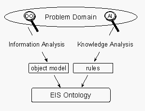
In practice and because of the high complexity of the systems to be built, the information analysis and the knowledge analysis cannot be performed separately. The modelling will rather be an iterative process that starts with the analysis of the information and system components to obtain a basic object model. This model consists of classes, relations, functions and object constants. In the attempt to formulate rules operating on this basic object model, one is likely to face a lack of words to describe certain rules and dependencies. This lack of words gives rise to a refinement of the object model. After some iterations the object model and the rules will provide a satisfactory description of the domain of interest.
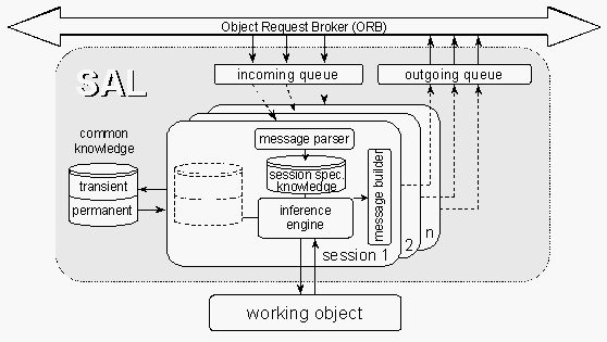
The last chapter dealt with the different levels of requirements concerning communication between software agents. We also have outlined how we meet these requirements and which standards are used. The implementation of the framework was another important step; the result is the so-called Service Agent Layer (SAL). While a service is a reactive software component, the SAL includes several abilities that are characteristic for agents: communication (social behaviour) and proactivity. The service together with the SAL can be regarded as an agent.
Before describing the architecture of the SAL in more detail, it might be helpful to introduce the notion of a session within the SAL. A session is a logical unit that is responsible for a conversation, i.e. it receives (related) incoming messages, reasons about them, stores and processes relevant data and sends out related messages. An agent can run different sessions simultaneously. Sessions can be created and deleted at runtime. There might also be an initial session which lives as long as the agent is running and takes over the proactive part of the agent, e.g. by advertising its service and abilities and by setting up contracts about the conditions of use.
Clearly, what happens inside a session is specific for an agent. In practice this lead to an abstract class for sessions which has to be implemented for each service attached to a SAL. On the other hand, there are many other parts of the SAL that are shared by all agents, including the message receiving, queuing and sending mechanisms.
Normally the SAL and the attached service will run within the same process. There are, however, cases where the service and the SAL cannot be compiled and linked together. Then special ways of data exchange have to be used, e. g. via DDE (dynamic data exchange), RPC (remote procedure calls) or a graphical user interface when a human user communicates via the SAL with other agents. These cases are very important because they allow re-using own or third-party services at low adaptation costs.
The basic architecture of the SAL is shown in Fig. 2. Incoming messages are put into a message queue from where they are routed to an appropriate (either already existing or newly created) session.
Inside the session, the next step can be very complicated: Appropriate reactions to the incoming message have to be found. This is supported by a rule-based system. The knowledge base of this system consists of session-specific knowledge and of common knowledge, which is shared by all sessions within a SAL. According to the content of the incoming message, the session-specific knowledge is updated. Depending on the knowledge (which now includes the contents of the message as well as results from previous messages) and on the rules of the inference engine, it is decided whether and how the incoming request is handled. Among many other possibilities, the session could
Outgoing messages are completed by the message builder and put into a queue. There is a thread pool whose threads are finally delivering the messages via CORBA to the recipients.
After this discussion of the communication framework and the Service Agent Layer, we want to give a description of the overall architecture of the Multi-Agent Systems developed in our department.
The distributed system we are developing has the structure shown in Fig. 3.
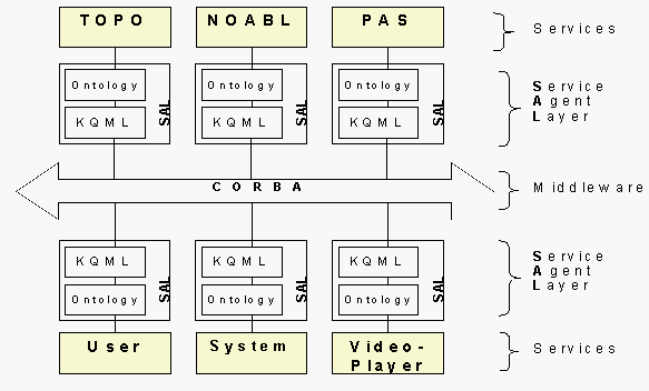
Fig. 3: Architecture of the Distributed System
Besides integrating the modules mentioned already as services at least two additional agents have to be included. These are the Repository agent and the Administration agent.
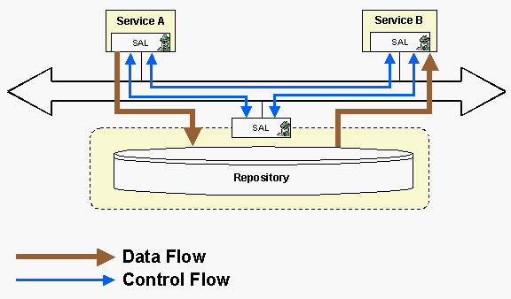
The purpose of the Repository agent is to exchange data between services. The exchange of large data via CORBA and the SAL is much too expensive. Therefore different ways have to be provided for this task. Fig. 4 illustrates the basic principles of the Repository concerning the usage and the separation of the data flow and the control flow.
The purpose of the Administration agent is to administrate the agents of the system and to coordinate their cooperation. Like the other agents the administration agent can be realised in various ways. Usually we prefer the so-called Strategy Service [7]. For the presented system however we have chosen an implementation which supports the user in managing the system via a graphical user interface (GUI).
The agent-oriented approach allows the development of different services operating at different locations and by different teams. By this distribution it is possible to use tools and computers which are most effective to fulfil a certain task within the multi-agent system. In the present scenario we have distributed work between the University Paris 6 and the University of Stuttgart. University Paris 6 took over the optimisation of the services NOABL and PAS and the validation of the calculations results by comparison with experimental data.
The pollutant atmospheric dispersion constitutes an important research theme of these last years. It is a question of assessment and control of the pollutant materials (chemical, radioactive, ...) in the environment. In accidental situations, it is necessary to predict in short laps of time the pollutant rate at build-up area. Generally, programs simulating the pollutant spread into atmosphere consist mainly of the parts:
To meet the requirements for accuracy and faster execution times, massively parallel processing will be used.
The NOABL (NOAA Boundary Layer) program [8] allows to simulate a mass-consistent windfield over complex terrains. Like any model it is an abstraction of the reality. For the purposes we are dealing, it is the most appropriate. This model considers a conformal coordinate system with a non constant vertical step. This variable step, smaller over the raising surface, allows the bottom boundary condition to be defined more accurately and secondly the option of variable vertical zoning improves the accuracy and economy of the model. The using of supercomputers is justified by the complexity of the model.
Mesoscale atmospheric models cover domains, the horizontal dimensions of which extend up to some hundred kilometers and the vertical dimension up to some hundred meters. The physical model of NOABL leans on a mass conservation law [9] with the appropriate boundary conditions. A simplified form of this equation has been used to represent the mass conservation, also called Diagnostic Equation (the time-dependent term being absent).
Let consider an initial divergent flowfield, components of which are given locally by . Let be
the correction necessary to eliminate the divergence [8]. The components of the resulting windfield will be given by the following system:
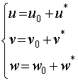
Some assumptions about the circulation of air masses (internal friction due to viscous effects may be neglected, air density variation is ignored, etc) ensures the existence of a single-valued perturbation velocity potential from which the correction windfield
will be computed. After replacing into the mass conservation equation, we obtain a Poisson Equation's:
In the case of flat terrain surface, the previous Cartesian Coordinate Model is well adapted and can be used. The problem becomes more difficult when complex terrain surfaces are to be considered within the study domain where the accuracy is highly dependent upon the finite difference resolution. To solve this difficulty, the vertical coordinate will be transformed in such a way that the terrain surface becomes a coordinate surface [10]. The expression of the Poisson's Equation in the Conformal Coordinate System will be the following one( represents the conformal coordinate,
the terrain surface,
, with
the constant altitude of the top of the mesh):
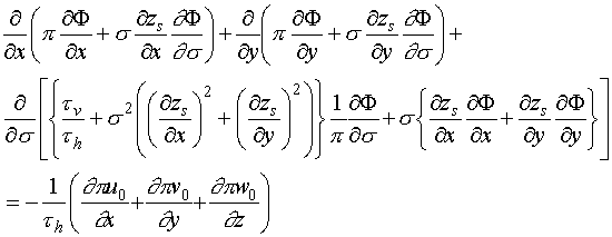
The algorithm used on the NOABL program to compute a free divergence solution for the velocity field is SLOR (Successive Line Over Relaxation) [11] followed by a Thomas algorithm for each column (solving of a linear system the matrix of which is 3-diagonal) [12].
An analysis of the serial version of NOABL program led us to the conclusion that it would be worth to parallelize only a part of this program, more precisely the part computing the perturbation velocity potential. So, at the beginning, in order to avoid the communications during the computing of the initial windfield, each processor will compute the initial windfield over the entire domain, and for the free divergence windfield computing, it will consider its sub-domain.
First of all, it is well known that, at a given iteration, the updated values of a column are used as soon as they are computed. So each sub-domain cannot start computing if a first column result has not yet been furnished from the previous sub-domain. Following this reasoning, the idea of parallelizing the SLOR algorithm is a very simple one. The computing starts at the first sub-domain. The first result column is obtained and is sent to the next sub-domain, the second one can start computing, and so on.
The SLOR algorithm adopted for the computing of the perturbation velocity potential led us to choose the geometrical form of parallelism. So, the parallelization of the NOABL program has been done by combining a pipeline scheme in one horizontal direction with a parallel scheme computing in the other horizontal direction. A rectilinear grid of processors has been used.
The first parallelized version has been obtained on MEIKO-CS2 parallel machine utilizing PVM library. The program has been written with Fortran 77. Simulations have been done with a computing domain having 150 points in the two horizontal directions (x-direction and y-direction) and 45 points in vertical direction. The results presented in the following (over CRAY T3E parallel machine) have been obtained with relaxation parameter value equal to 1.5. The two possibilities of program stopping are: first a minimum residual value has been taken equal to 0.05 and second a maximal number of iterations has been fixed equal to 5000.
In order to compute the Theoretical and the Real Speed-Up, runs have been made on one processor of the parallel machine in order to determine the part (in execution time terms) of the program having been parallelized. It is with this aim in view, we have used the Amdhal law for computing the Theoretical Speed-Up:

where:
: Part of the program having not been parallelized
: Number of processors used for program's runs
The NOABL program has been implemented on CRAY T3E parallel machine using MPI library. The running times, as well as the theoretical speed-up and the real speed-up obtained on CRAY T3E, are represented in the following Table.
| Processors' Number | Running times (s) | Theoretical Speed-Up | Real Speed-Up | Efficiency (%) |
| 1 | 7167.30 | 1 | 1 | 100 |
| 2 | 3778.29 | 1.98 | 1.90 | 94.86 |
| 3 | 2611.89 | 2.94 | 2.75 | 91.47 |
| 5 | 1705.86 | 4.79 | 4.20 | 84.03 |
| 6 | 1448.70 | 5.69 | 4.95 | 82.46 |
| 10 | 976.52 | 9.12 | 7.34 | 73.40 |
| 15 | 739.56 | 13.03 | 9.69 | 64.61 |
| 25 | 575.74 | 19.86 | 12.45 | 49.80 |
The SLOR algorithm is not the best-adapted algorithm for being parallelized. The differences noticed between the Theoretical Speed-Up and the Real Speed-Up are due to the combined parallelization scheme ( pipeline + parallel ) and the increasing part of processors communications time with the number of processors. The efficiency decreases with the number of processors because of the particularity of the SLOR method.
However, it is interesting to observe that after parallelization the running times have been noticeably improved. The parallel machines have permitted to obtain a real improvement of code performances. With 150x150x45 grid points, we obtained 108 Mflops with two processors up to 960 Mflops with 50 processors.
The parallelization of the NOABL program (the serial version was furnished by IKE) has been realized as a part of a common collaboration between OECD, IKE and CNAM. Runs on CRAY-T3E of IDRIS-CNRS have been done through the Project n: 974111.
The program PAS as an important part of the MESYST system is used for the simulation and the computing of the atmospheric pollutant dispersion. The physical model of PAS leans on the lagrangian model. So the dispersion phenomena has been modelized considering a great number of particles which are emitted by the source and held by the wind. At the end of a given period of time we consider the number of particles at each grid cell and after that, the concentration of the pollutant at each grid point will be computed.
The mathematical model describing the displacement for one particle during a time step equal to is given by the following formula [13]:
where represents the coordinates of the new position occupied by the particle,
the old position of the particle,
represents the displacement due to the presence of the wind and at last the term
takes into account the movement of the particle as result of the diffusion.
To compute the displacement due to the windfield we have considered the results provided by the NOABL program. Wind velocity at the particle position has been calculated by the
weighted interpolation of wind vectors on the eight grid points which surround the particle. Equation is:

where is wind vectors at grid
and
is the distance between particle and grid
.
An important part of the PAS program is this one simulating the displacement of the particle due to the diffusion phenomena. We have implemented two algorithms for this purpose.
The first one considers a Brownian Model. The fluctuation steps are calculated by a simple distribution function which has a standard deviation:
The diffusion coefficient are derived from the Pasquill-Gifford theory [14] according to the atmospheric stability category determined from routine measurements. The mathematical expression for the diffusion coefficients are the following ones:
The values for the parameters are provided by the experience and depend on the stability conditions.
represents the wind velocity at the particle point and
gives the distance of the particle from the emission point.
The random values for the displacements on each direction have been obtained by a random number generator following a Brownian law. So we will have for the mathematical expressions:
represents a Brownian distribution function with the three series generated for each direction being independent.
The numerical model in PAS employs a uniform distribution function in order to accelerate the calculations. After these modifications the expressions for become:
For computing the concentration of the pollutant at each domain point, a Monte-Carlo Method has been utilized. We consider a great number of particles that we follow during their displacements. We associate to each particle a weight expressed on kg for example. After a given period of time we compute the number of particles present on each grid cell and the pollutant concentration at the considering point can be calculated. We will repeat this operation several times and an average for the concentration value will be calculated in order to have a better approach of the reality.
The Monte-Carlo method permitted a parallelization of the PAS program to be done without difficulties. The code parallelization has been done by considering the particles set which has been divided into sub-sets. Each sub-set has been dealt with by one processor. So a set of processors has been used for the program runs.
The execution model was SPMD and MPI library has been utilized in order to assure the program portability. Our objectives were: first to reduce the execution times and secondly to improve the accuracy of the model by increasing the number of particles considered. The following table presents some results obtained after the parallelization of the program on CRAY T3E of CNRS-IDRIS at Orsay.
| Number of processors | Execution time (s) | Efficiency (%) | Speed-Up |
| 1 | 400.55 | 100.00 | 1.0 |
| 2 | 211.53 | 94.68 | 1.9 |
| 4 | 107.41 | 93.51 | 3.73 |
| 5 | 85.67 | 93.23 | 4.68 |
| 8 | 56.22 | 89.06 | 7.13 |
| 10 | 45.96 | 87.16 | 8.72 |
| 20 | 28.39 | 70.55 | 14.11 |
The second algorithm we have implemented for simulating the diffusion phenomena is based on the fractional Brownian model. This case represents a generalization of the Brownian model by considering that the particle displacement due to the dispersion does not depend on but the dependency is like
where
in the case of atmospheric dispersion. Richardson proposed the value of 0.66 [15].
With this new model, the mathematical model becomes:
where indicates a random number distributed following a fractional Brownian law. Fig. 5 and 6 explain the differences existing between a Brownian diffusion and a fractional Brownian one.
Fig. 5: Particle displacement stays "close" to zero using the Brownian model.
Fig. 6: Particle displacement are greater using the Fractional Brownian model.
As one can see, the distance of one particle following a fractional Brownian distribution, from the initial point is greater than that of one particle following a Brownian distribution. In other terms, the particles cloud in the first case will be more extended that this one on the second case.
For simulating the fractional Brownian motion, two algorithms have been implemented:
The second one being more efficient and faster than the first, it has been utilized for our simulations. The results obtained in term of parallelization (Speed-Up and Efficiency) with the fractional Brownian model are as good as those obtained with the Brownian model. The execution times of the PAS program with the fractional Brownian algorithm are greater than the execution times with Brownian one, but the new model permitted us to improve the accuracy of simulation, validated with SIESTA experiments.
The aim of the project named SIESTA (SF6 International Experiments in STagnant Air) was to obtain knowledge of the general nature of the turbulence, advection and atmospheric dispersion [16].
The SIESTA Experiments have taken place in a Swiss region (Aare Valley). The dimensions of our study domain were 30 km on X-direction, 30 km on Y-direction and 1100 meters on the vertical direction (with 120 points on X and Y and 22 points on Z). For studying of the atmospheric dispersion, tracer has been used. This is a chemically stable and non-toxic gas.
For the validation of our dispersion model, we have considered the day of November 30, 1986. During this day a weak south-west wind has been noticed and the general atmospheric conditions were stable. For the simulations, the period of time from 8 a.m. to 2 p.m. (let be 6 hours in all) has been considered. During this period some meteorological stations have provided data concerning the wind speed and the wind direction. At the same time, the coordinates of the points where these measurements have been taken, have been given. With these meteorological data we have simulated the windfield at each 30 minutes. This windfield has assumed to be constant during the 30 minutes following. So we have computed 12 windfield at all.
Consequently, with these 12 windfields we have obtained 12 tracer clouds, providing the position of tracer at each end of the period. By SIESTA Experiments, we have been given the values of tracer concentration at a given number of domain grid. In order to compare the accuracy of our two models (Brownian model and fractional Brownian model), we have computed the distance between the corresponding tracer points (real measurements and values obtained by simulation with the two models). The formula used is the following one:
By applying this formula in our two cases, we have obtained with the Brownian model a distance which were greater than this one obtained with the fractional Brownian model allowing us to have a better description of the reality with the fractional Brownian model.
The two colour images given in the appendix present the position of the tracer cloud at 2 p.m. calculated with the Brownian model (file brownorm.ps) and the fractional Brownian model (file browfrac.ps), respectively.
The functionality of an approach as the one presented in this paper becomes most obvious by giving a demonstration. Therefore we have added a video documentation of the demonstration given at the oral presentation of this paper (files demo.mpg and demo.avi, which is more legible). A version of this demonstration including an audio explanation will be provided at http://www.ike.uni-stuttgart.de/www/about/cug.html.
The parallelization of different modules allowed us to obtain a high performance product by decreasing obviously the running times. At the same time, the choice to parallelize by using the MPI library made our system portable.
The agent-oriented approach seems to be a powerful technology whose importance will probably rise during the next decades. It is currently applied as a basic technology of three different projects within the Department of Knowledge Engineering and Numeric at Stuttgart, including a real-world project to monitor and simulate the dispersion of radioactivity within an emergency system in case of a nuclear accident.
This work was partially supported by the Ministerium für Umwelt und Verkehr Baden Württemberg, project GLOBUS, by the Deutsche Forschungsgemeinschaft Bonn, project Graduiertenkolleg Parallele und Verteilte Systeme, and by the OECD and IDRIS-CNRS project No. 474111.